7 MHz SSB Transceiver
POWER SUPPLY
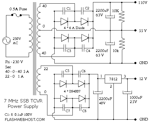
The transceiver requires 12 volt for most of the circuitry and 120 V for the final. The power supply should be capable of supplying the maximum current required with good stabilization. I used commercially available 40 - 0 - 40 5A transformer. The transformer have 6V, 9V, 12V and 22V windings also. The transformer cost me around Rs: 370. Power supply provides 110 Volt 2.5 Amps or 55 Volt 5 Amps. Three-pin regulator IC is used for regulating 12-volt supply. Good heat sink should be provided for regulator IC.
All diodes in the bridge rectifier are shunted with 0.1 uF 100 V capacitor (C1 to C8) to keep the diode protected from high voltage transients on the AC line as well as reduce inter-carrier hum modulation of RF that may be picked up by the mains. Always use fuse in 120 V supply line. This can avoid hand full of burned IRF. It also protects the power supply itself. My final consumes around 1 A at peak. I used 0.5 A fuse; it won’t go QRT with 1 A peak current. It is better to use a fuse that can just withstand the peak current.


